|
Introduction With the referencefrequency of PE1FOD and PA3AIN from the March issue of CQ-PA in 2005, which will serve to my counter as a right timebase, I use a Jupiter GPS module TU30-D140. Because the output of 10kHZ is always present, even if no satellites are received, I went looking for a circuit to be able to see that enough satellites are received and there is a so-called lock. On the site of Dili-Soft , I found a GPS monitor. Initially I used this scheme. Also used the software of that site. Here they use another GPS receiver, which can be programmed which NMEA-line will be in the output. With the Jupiter this is not possible. Therefore I changed the program so that only the line that starts with $ GPGGA is used. Also changed the output to my own wishes. |
||||||||||||||||||||||||||||||||||||||||||
|
|
||||||||||||||||||||||||||||||||||||||||||
|
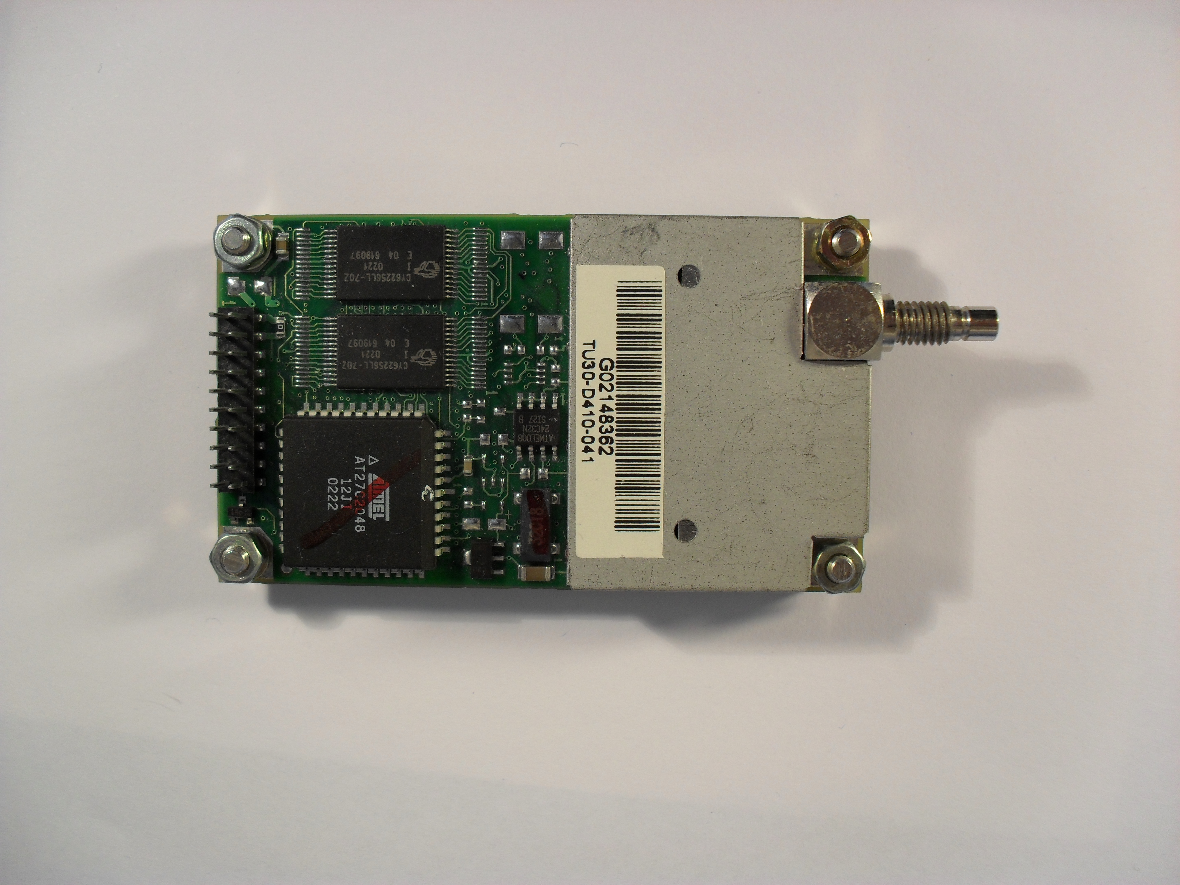
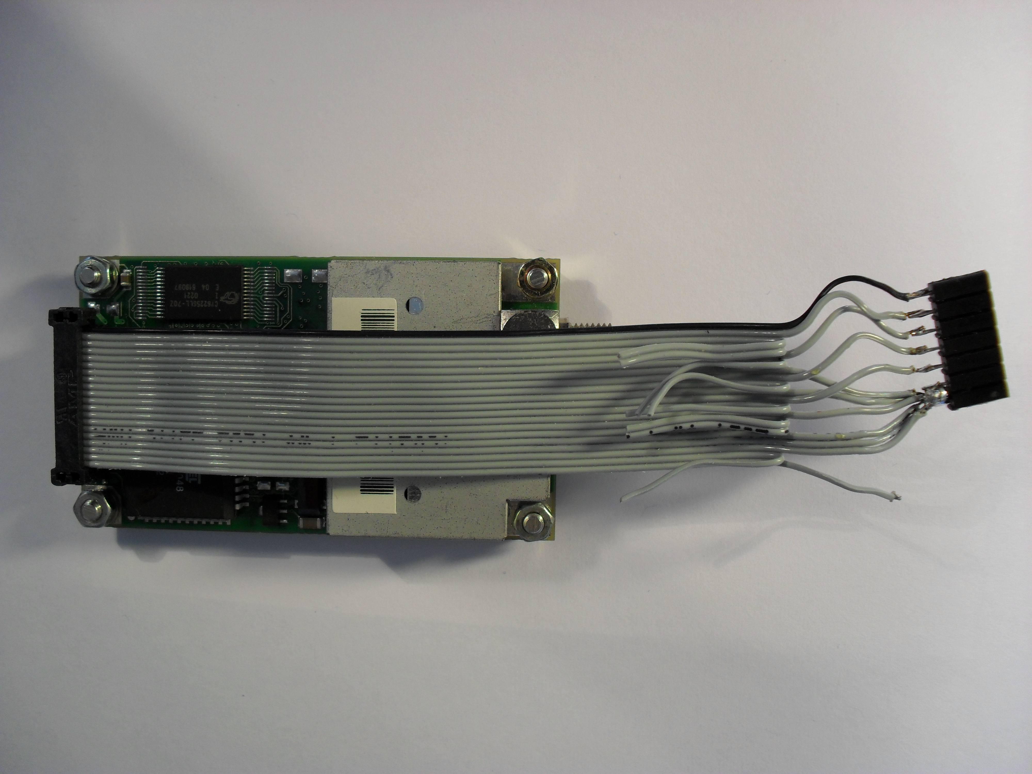
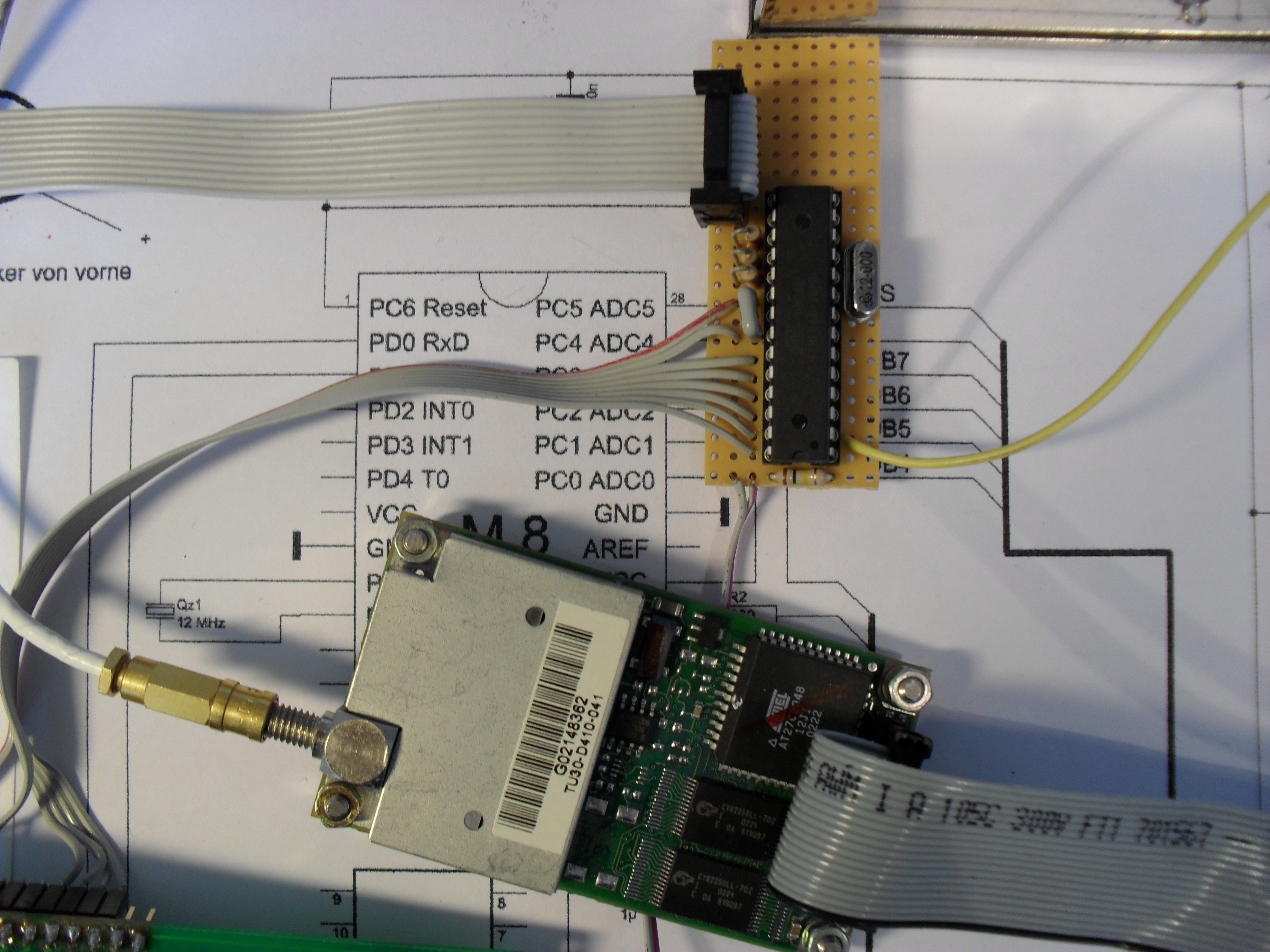
Jupiter GPS module TU30-D140 This GPS module contains a 20-pin connector. This is a different size. Instead of the usual distance between the pins of 1/10 inch this is 2 mm. With my module I had fortunately a suitable connector. Due to the abnormal size, the flat cable is narrower. Therefore I only soldered the used wires to a 1/10 inch connector. The connections of the module (see datasheet ) On the diagram that follows later the used connections are shown. |
||||||||||||||||||||||||||||||||||||||||||
|
||||||||||||||||||||||||||||||||||||||||||
|
||||||||||||||||||||||||||||||||||||||||||
Click on photo to enlarge |
||||||||||||||||||||||||||||||||||||||||||
|
|
||||||||||||||||||||||||||||||||||||||||||
|
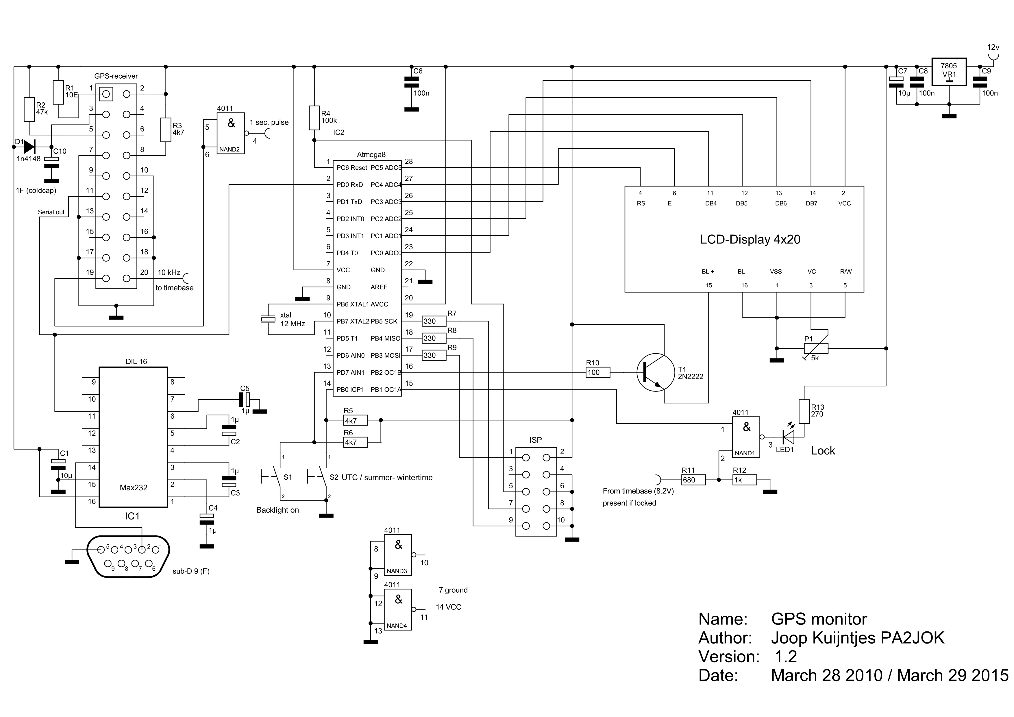
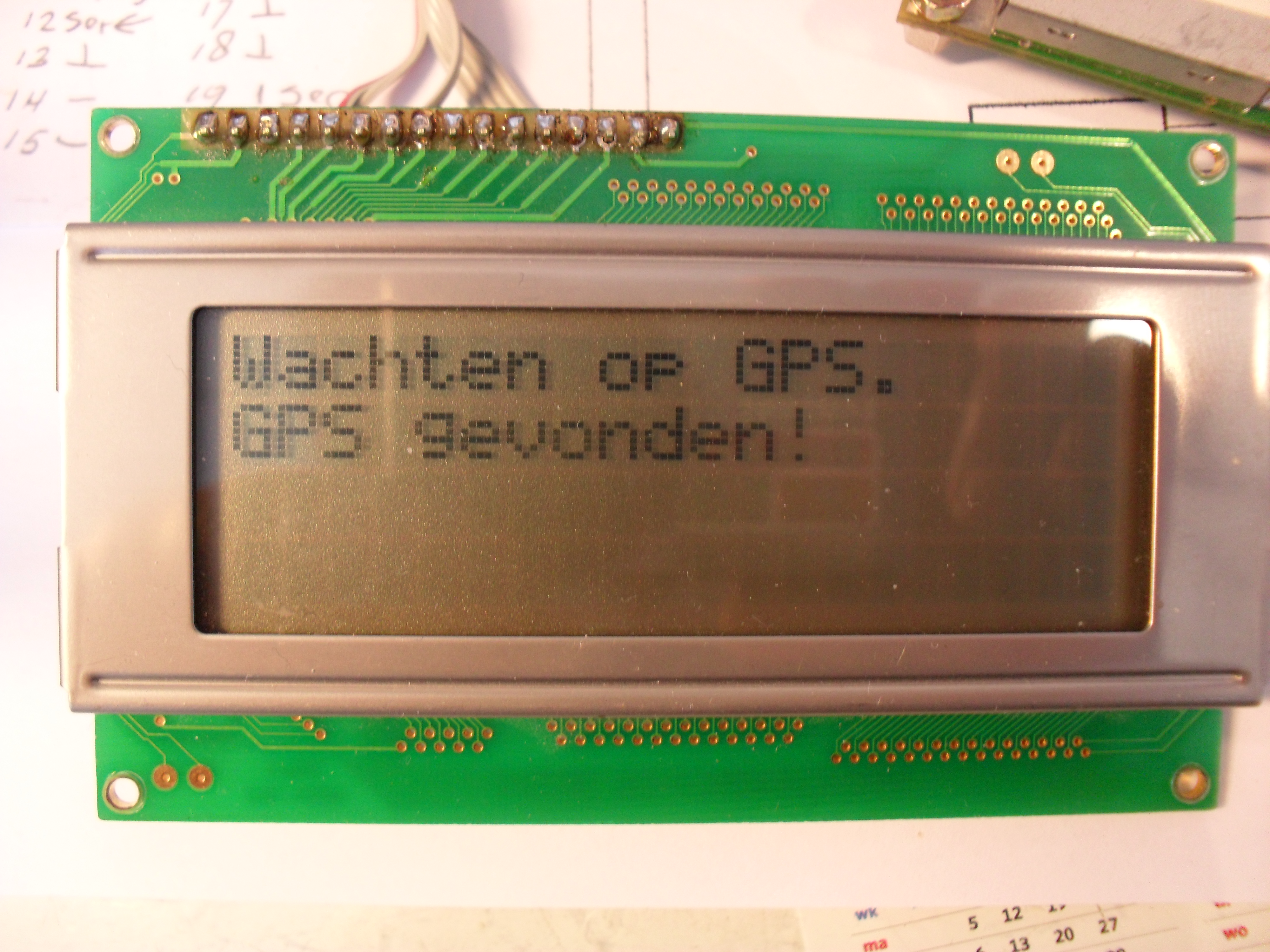
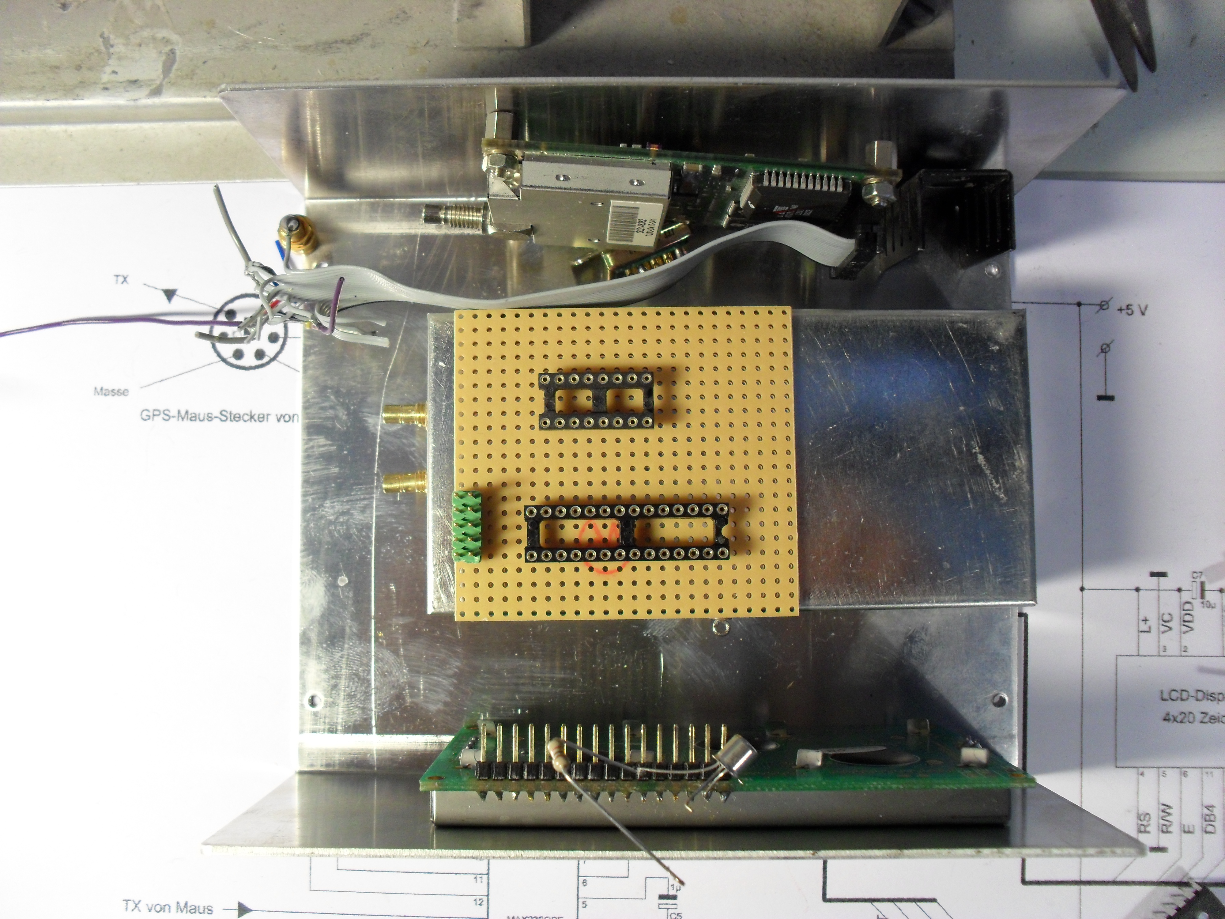
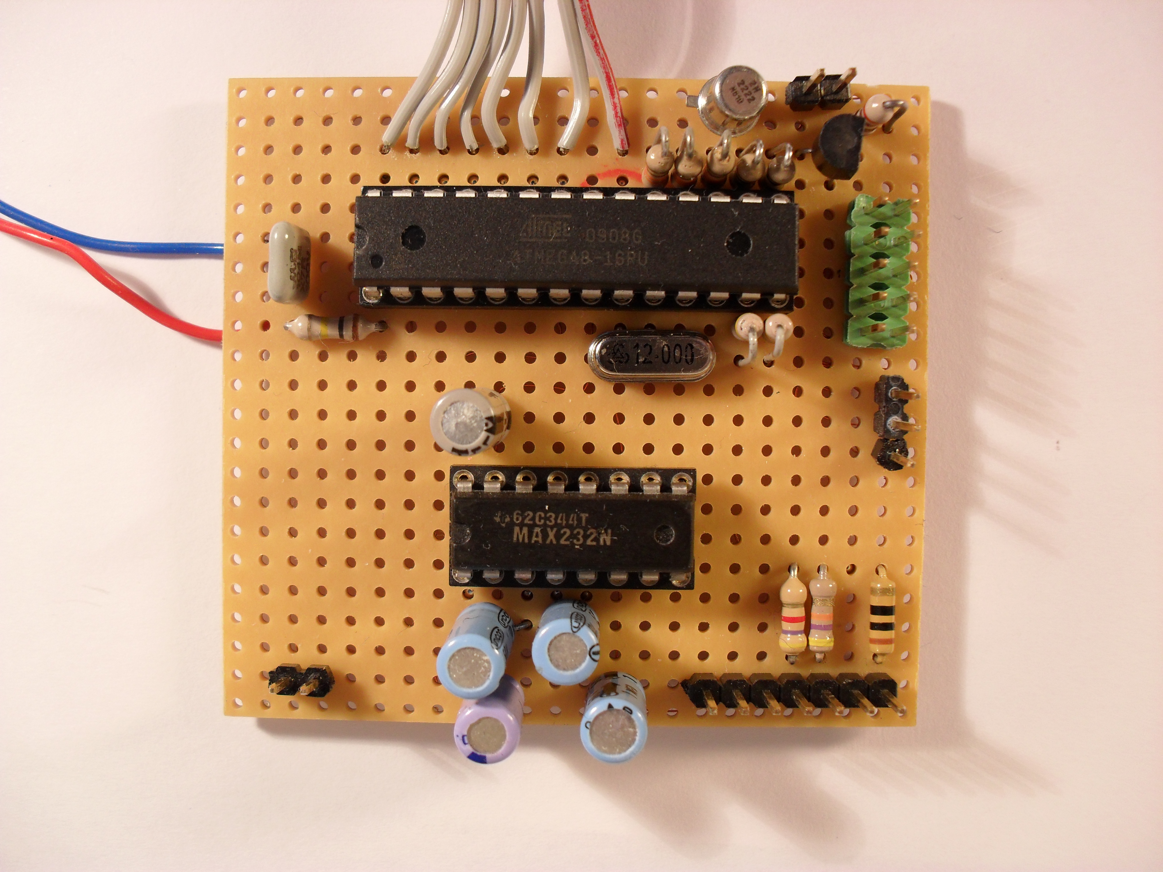
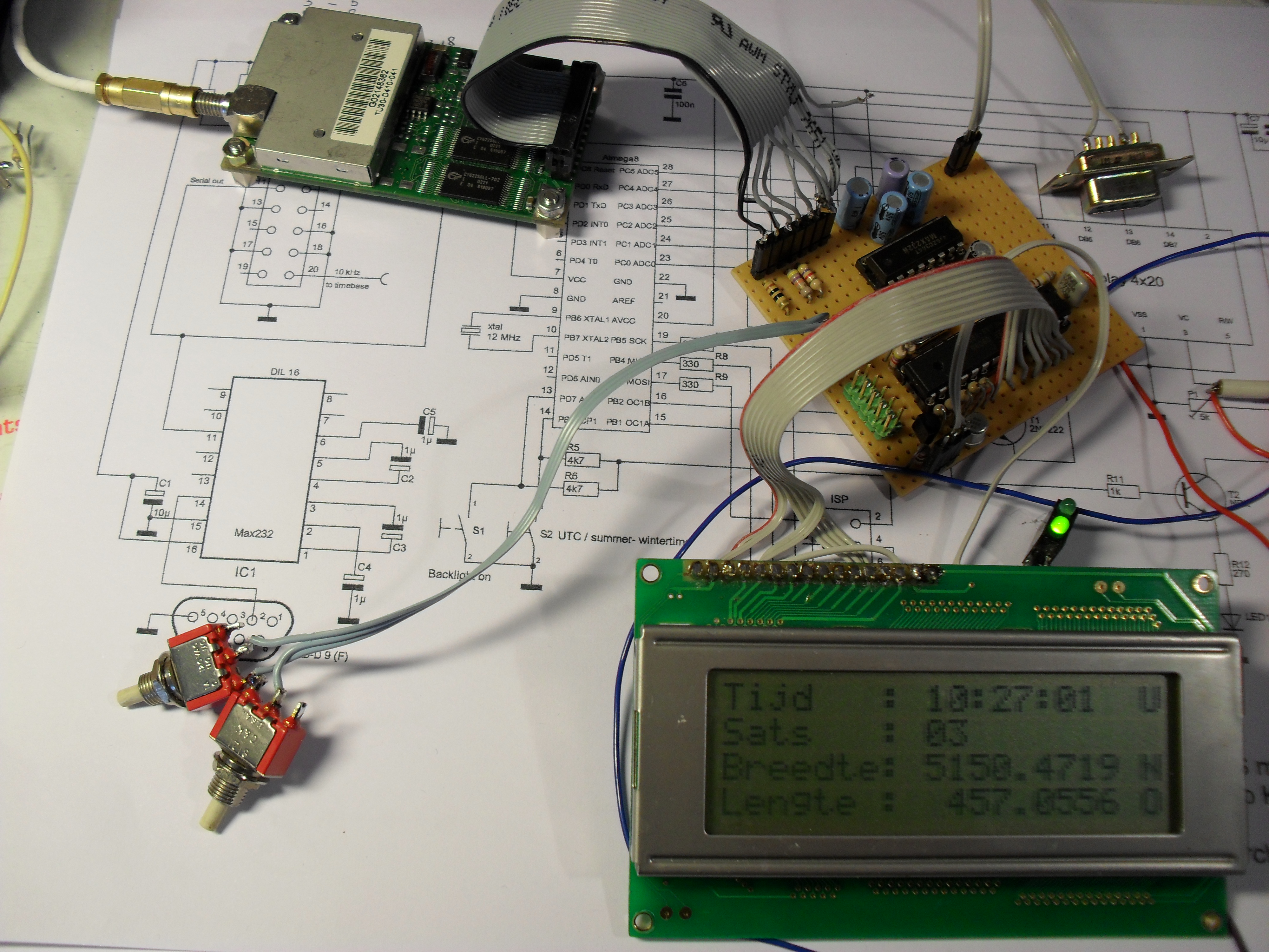
Diagram GPS monitor The heart of the circuit is formed by an ATmega8-16. The NMEA output from the GPS receiver is connected tot the RxD input. Only the line that starts with $GPGGA is used. The time, position, number of satellites and the indication that a lock is received are extracted from the $GPGGA-line. The time is in UTC, with switch S2 it can be set to UTC, winter- or summertime. The backlight of the LCD display is on at the start and is switched off about 2 minutes after a lock has been received. With switch S1 the backlight is switch on for about 2 minutes. LED1 is blincking while waiting on the lock and is on when a lock is detected. The Max232 is used to convert the NMEA TTL level signal to RS232 level, so the signal can be used on a PC with a freeware program such as VisualGPS. Via the ISP connector you can program the ATmega. Click on the diagram to enlarge or download GPS_monitor.pdf In the diagram is says 'From timebase (8.2V), present if locked'. This is a connection to pin 7 off U6B, the TLC272 in the above mentioned diagram from PE1FOD. |
||||||||||||||||||||||||||||||||||||||||||
|
||||||||||||||||||||||||||||||||||||||||||
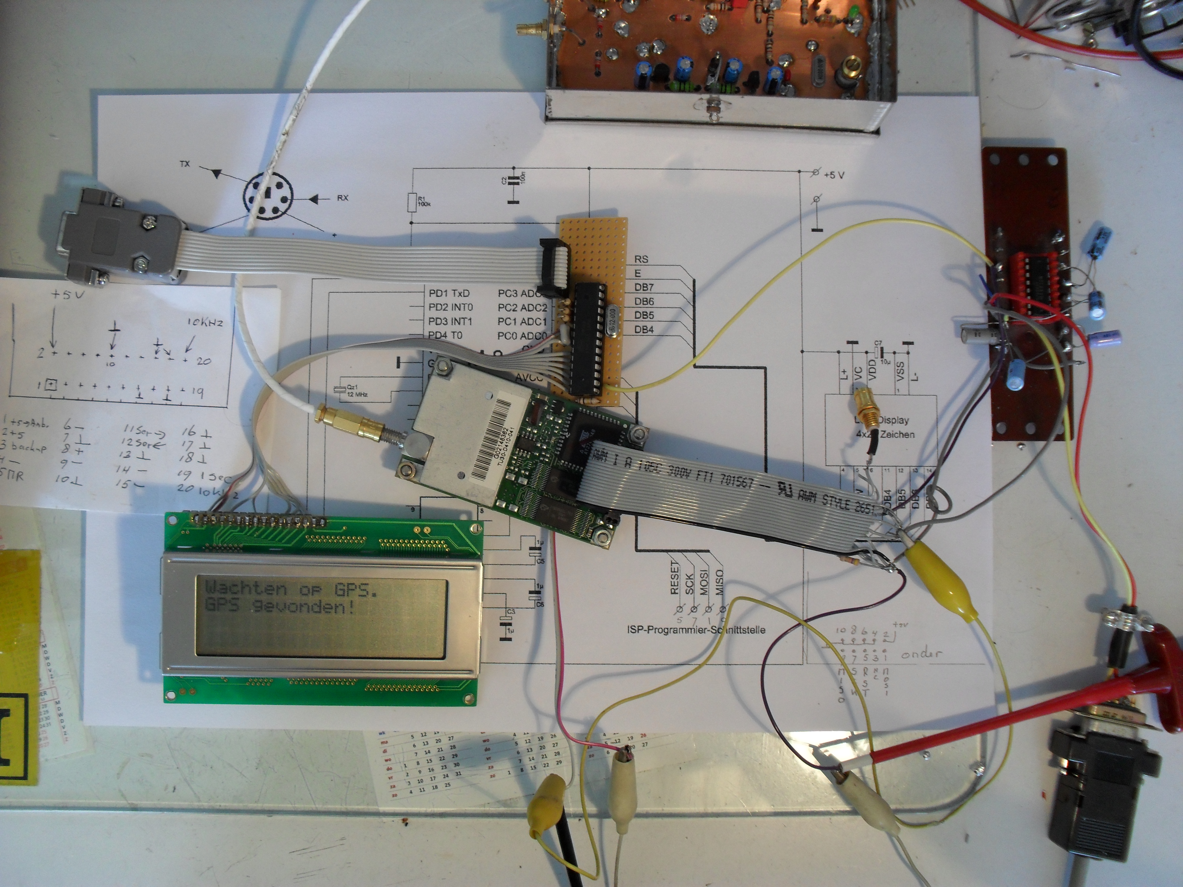
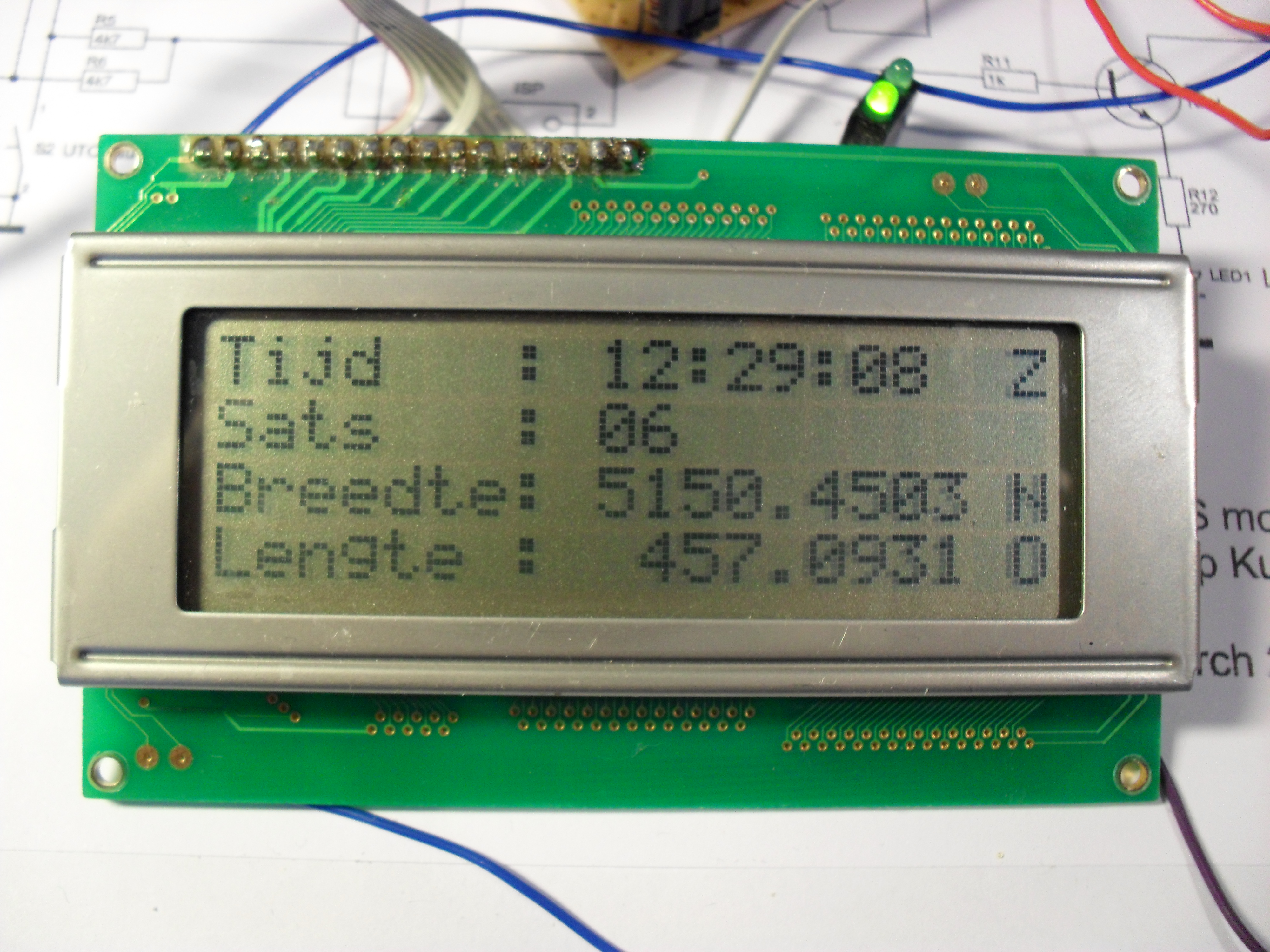
| First test setup: | ||||||||||||||||||||||||||||||||||||||||||
|
||||||||||||||||||||||||||||||||||||||||||

Click on photo to enlarge |
||||||||||||||||||||||||||||||||||||||||||
|
|
||||||||||||||||||||||||||||||||||||||||||
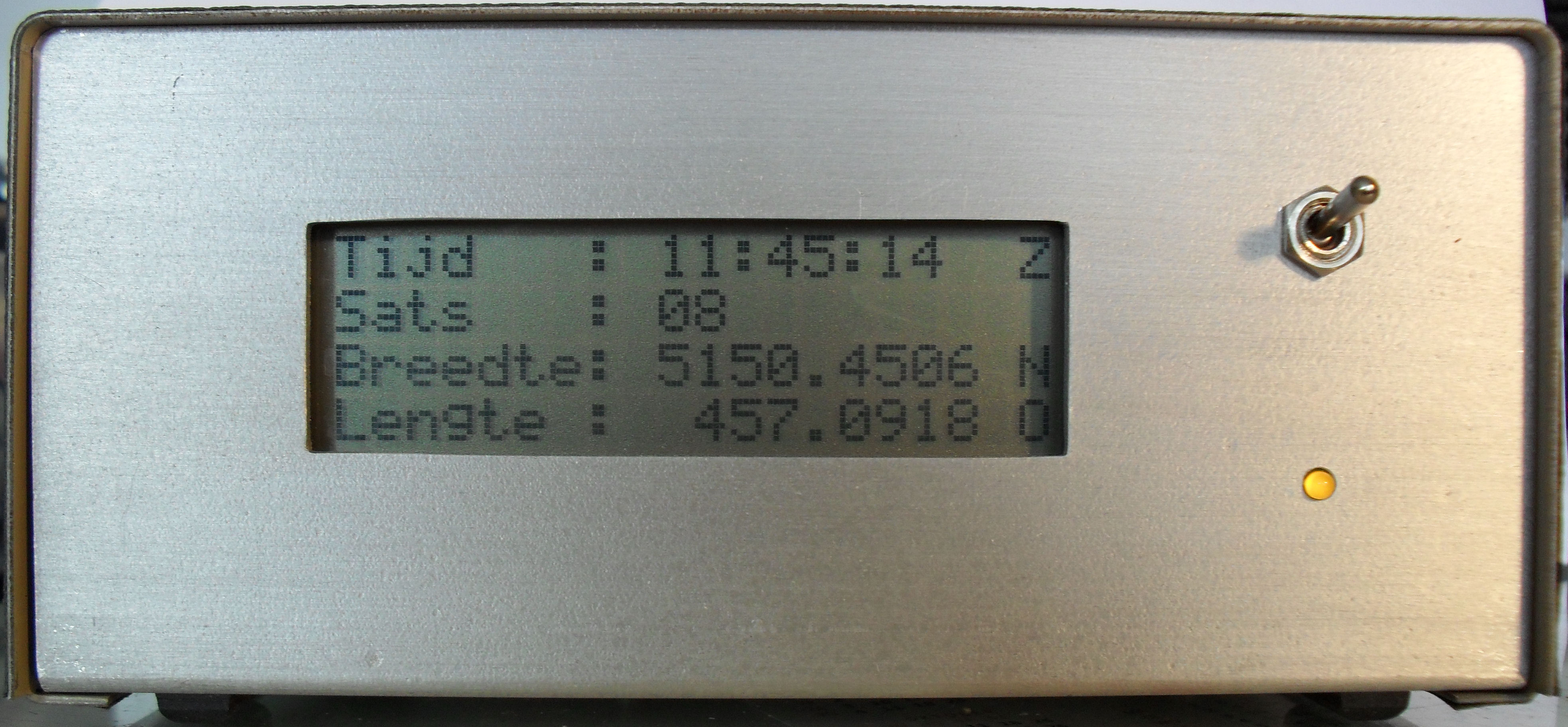
| Final construction: | ||||||||||||||||||||||||||||||||||||||||||
|
||||||||||||||||||||||||||||||||||||||||||
|
||||||||||||||||||||||||||||||||||||||||||

|
||||||||||||||||||||||||||||||||||||||||||
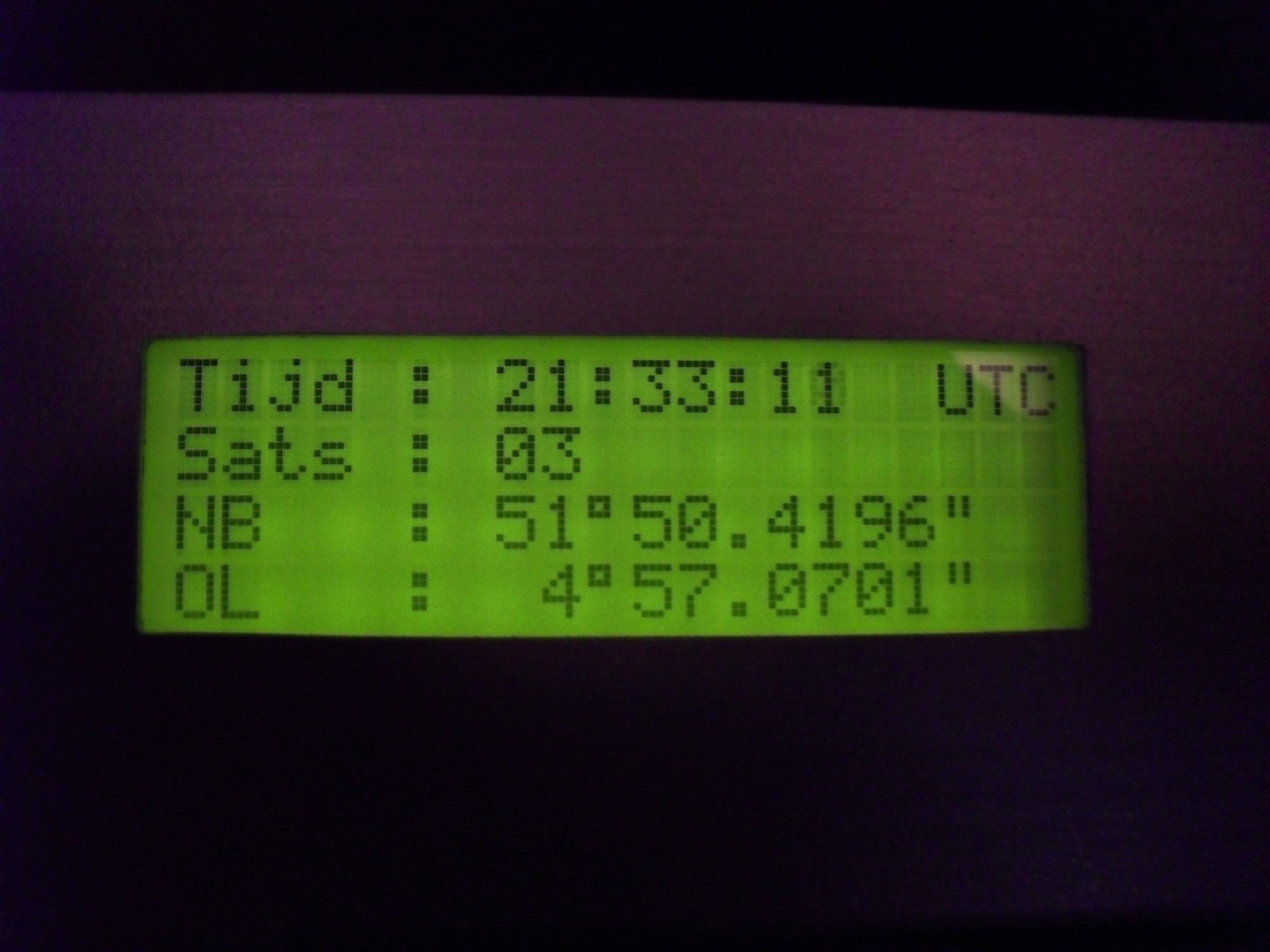 New version (1.5) display, grads and minutes in another format..
Click on photo to enlarge |
||||||||||||||||||||||||||||||||||||||||||
|
|
||||||||||||||||||||||||||||||||||||||||||
|
The program The program is written in Basic. To build and compile I use BASCOM-AVR. With the demo version you can compile upto 4KB. The ATmega is programmed in the circuit. For this I use a diagram from Elektuur May 2006. I can't publish this diagram. But there are several diagrams for RS232 or LPT on the web. I use the program PONY-prog2000 to write to the ATmega. The Fuse bits SUT1 CKOPT are turned on, the rest I left off. Here you can download the source and the compiled hex file as a 1.3 zip-file or 1.5 zip-file . |
||||||||||||||||||||||||||||||||||||||||||